11-26-05 : COMPLETE!!
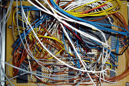
This is the end result of my transfer from breadboard to perfboard. All 17 chips are contained here, as well as the debouncing resistors and capacitors and the current limiting resistors for each of the clock face LEDs. I managed to somehow save room for the buzzer in the upper right hand corner of the picture, too. The wires are mostly color-coded. Most of the blue wires are related to the sensors. The yellow wires are for lines related to the clock, and the orange wires are for the alarm functions. Grey and white wires are used over the board for the buttons on the box, and on the board grey is the ground line and white connect the LED resistors to the enable outputs. On the board, the purple wires are for Vcc.
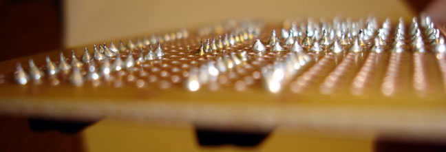
This is one of my favorite images of the project. All the solder points holding the 17 logic chips in place on the board look very nice. Once all the wires went into place, however, this backside got a lot messier. It was also the bane of my existance for a while, since a poor connection cause a few late night hours of frustration when the finished product would not work as it was supposed to. Fortunately I got it figured out and all it really took was melting 2 points more solidly together.
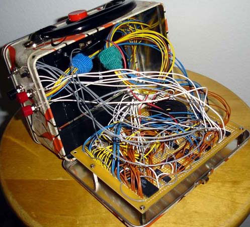
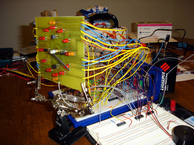
Here the lunch box that holds the whole thing together is opened up. The etched clock face is in place in the front of the box, and the perfboard is attached to the back of the back. The wires connecting both boards fill up a lot of the empty space in the box. You can also see the large OFF button on the top of the box, as well as the clock and alarm time set black and red buttons along the side. Above those are the display switch and the alarm active slider switch.
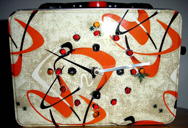
And here is the finished product. I think it looks really great. It hadn't occured to me before, but the design on the lunch box is sort of a throwback to the birth of the transistor, which is a nice byproduct.
11-22-05 : Etching the Face
Here I have the fully etched clock face attached to the breadboard. It looks like quite a mess.
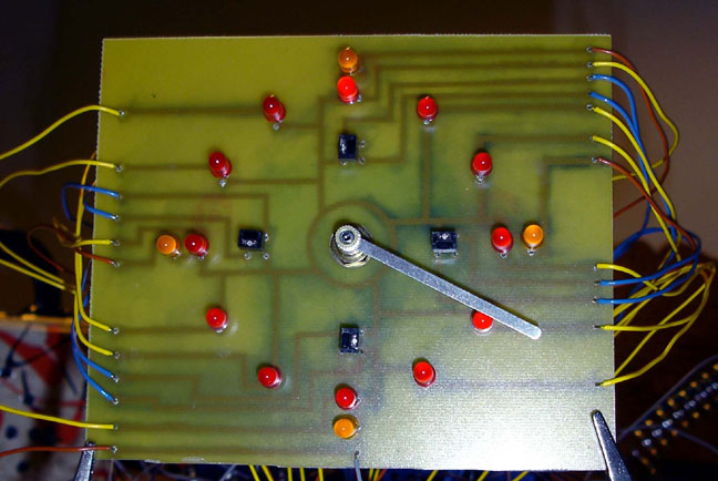
A close-up of the etched clock face reveals the etching pattern laid out on the back side, as well as all the LEDs and sensors already soldered into place.
11-16-05 : Sound the Alarm
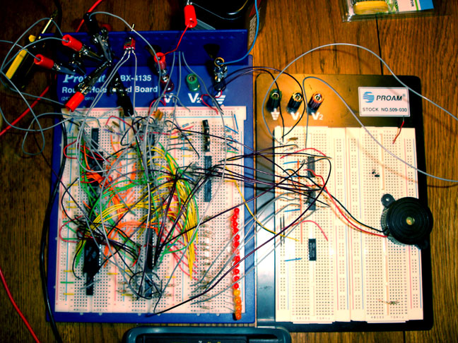
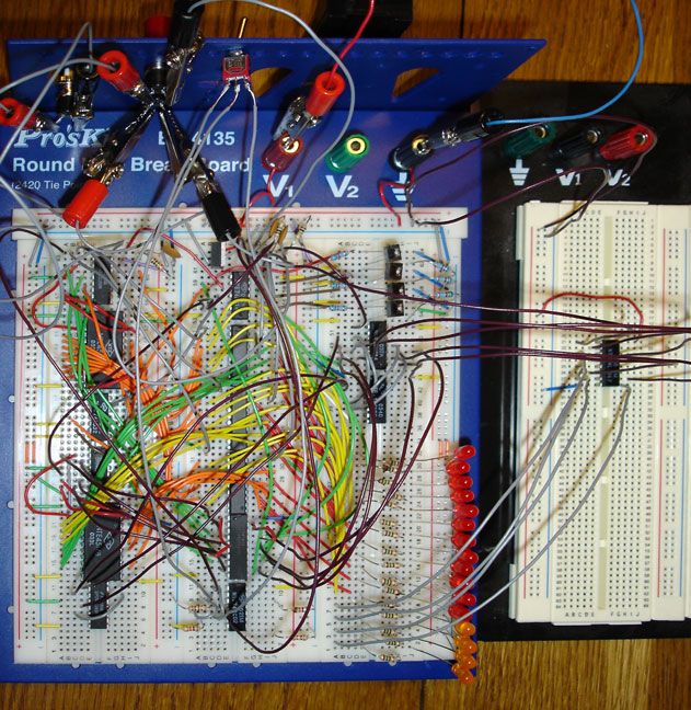
This is my entire layout at the point where I got the entire system working. I ended up with 2 more chips on the overflow board; they are an inverter and a D flip-flop. The inverter is an unfortunate addition. It turns out the output from my 2-to-4 decoder is active-low, so all the outputs were opposite of what I wanted to use. At first I decided to just run the outputs through the inverting Schmitt trigger since it was right there and had plenty of spots open. Once I debounced the giant OFF button, though, all the Schmitt triggers were used, and I ended up needing to invert a signal going to the flip-flop. There was no avoiding an additional chip. You can also see the alarm buzzer sitting there.
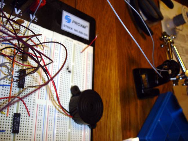
Here's a closer image of the alarm buzzer. It's a piezo electric buzzer that works off of voltages between 3 and 6 volts, which is perfect for this application. It has a subtly pulsing output and uses a voltage in a range the chips can put out. It's also a decent size and should fit into the final package nicely.
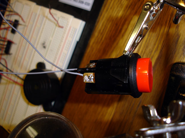
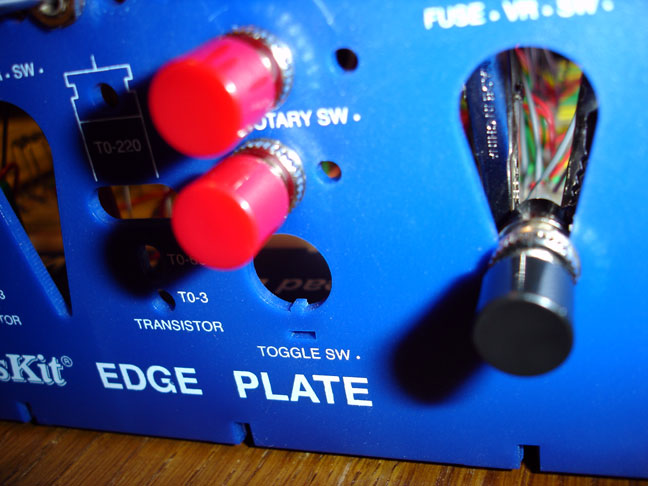
For the alarm OFF button, I wanted to use a large button. This was the best one I could find, and it does its job well.
11-14-05 : Hardware
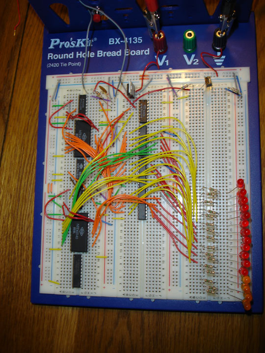
This is what my breadboard looked like when I finished on for the day on the 14th. I'd finally done enough work and added enough chips that I had to use my old breadboard from logic lab. I really didn't want to have to use two boards, but I'd already squished as much of the work onto the first board as possible. The chip on the right is a tri-state enable that I'll need to turn on the 4 orange LEDs whenever the clock is in "alarm set" mode. Otherwise people wouldn't know what time they were setting the alarm for!
These are the buttons I'm using for the clock hour set and the alarm hour and minute set. Not terribly exciting, but necessary nonetheless.
This is what it takes to debounce just those three push buttons. So many wires to keep track of, it's sort of counter-intuitive when trying to set them up.
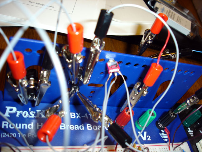
I just thought it'd be funny to take a picture of all the alligator clips I had to use for testing this circuit then make a reference to Alligator Alley. There are even more than pictured here.
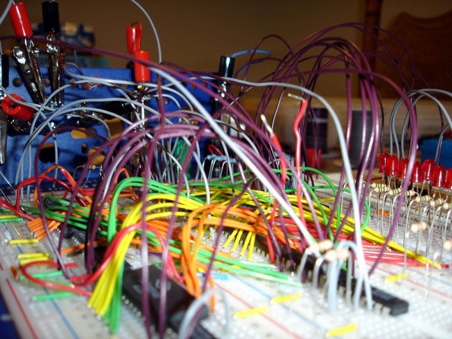
Welcome to the jungle.
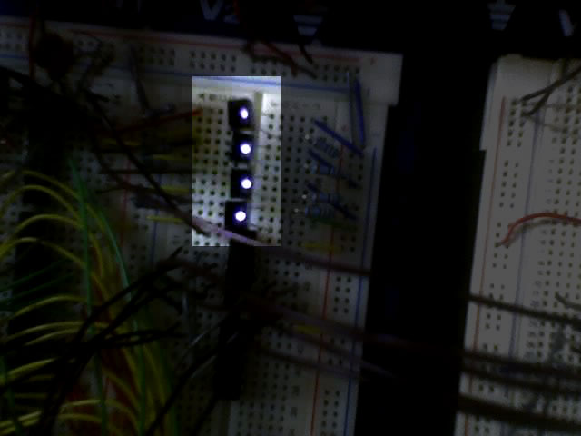
I finally got all 4 sensors hooked up, and here is proof that all 4 are emitting infra-red correctly.
10-30-05 : My collection of assorted wires
I hit a roadblock last week so I haven't done much since then. I realized I needed another counter like the ones I'm already using. I had a divide-by-2 counter that I thought would work perfectly with the 2-to-4 decoder for keeping track of the 15-minute alarm segments. However, when I started reading the datasheet more carefully, I saw it was a ripple counter and could have problems changing the outputs correctly. So back to the store I went, and since then I've been busy with work and other school stuff.
Up to that point, though, I'd had a lot of work done since my last update.
From my initial pictures you could tell my wires were becoming messy and difficult to look at. As you can see from this new picture, I have rewired the whole thing, making it easier to keep track of what's what. That took a good chunk of time, and I'm surprised there weren't more problems.
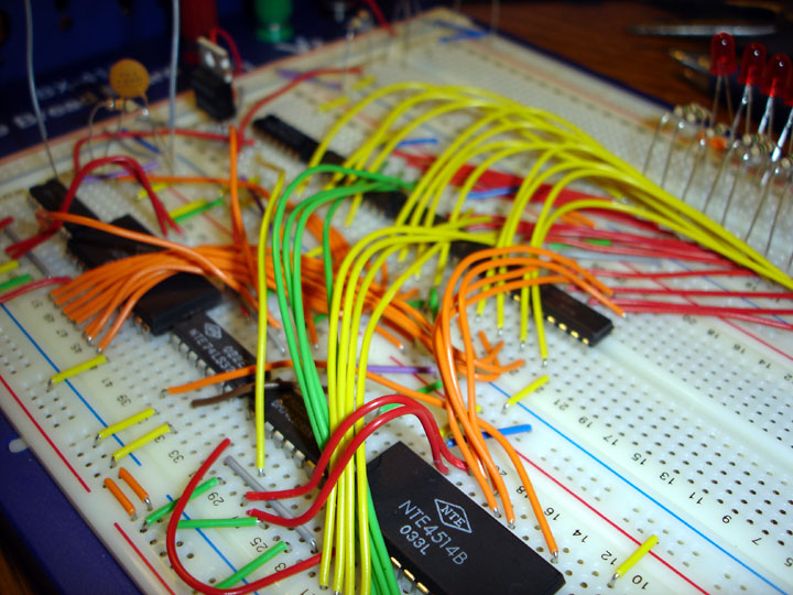
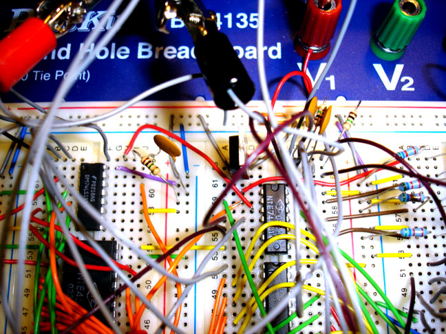
This is just a closer view of all the chips on the board so far. I have 2 sets of binary counters, 4-to-16 decoders, and tri-state enables to account for both the clock display and the alarm display. The counters and decoders are along the far left of the board, with an OR gate in the middle. Down the middle row of the board are the Schmitt trigger and 3 chips that have 2 sets of 4 enables each [for a total of 24]. I still need a few more enables to get the display switch working the way I want, as well as what I think will end up being a flip flop to trigger the alarm buzzer. I need to save space for the other push button and it's debouncing circuitry, too. The breadboard has filled up fast.
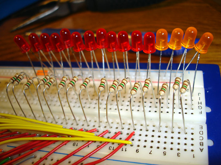
This is a picture I'm fond of. All the red LEDs will indicate the hours on the clock face, and the orange LEDs will indicate the 15 minute divisions at which the alarm can be set [in addition to the hourly setting].
And I won't forget that I hooked up 3 more of the reflective object sensors. They are waiting for the new counter and decoder, but I have checked and they are emitting the IR signal like they are supposed to. Hooking up the counter and decoder should be easy. From there it's just a matter of taking wires down to the 8-bit comparator I was waiting on before. It's all hooked up and ready to go from the sensor side I think. It's been a week or so since I've really looked at it, but a quick look and I should be able to pick up where I left off quite easily. Once I get that all working like I want, I'll have to figure out how to set and disable the buzzing alarm. I've got some ideas already, and so far in this project I've been pretty good about getting my ideas to function the way I want. I'm pretty optimistic about finishing in plenty of time and being able to "relax" my last few weeks of school.
10-16-05 : Clock Design - More parts
Since my last update, I've gotten a lot accomplished. I added the 4-to-16 decoder and connected all 12 LEDs to it. Got the counter working again, but then mysteriously the sensor stopped working. The IR emitting diode in it won't emit anymore. I think it has to do with the plastic housing of the part and how difficult it is to get the leads into the breadboard. I had to use a bit more force than I would have liked, and then the IR emitter popped out of the housing. The IR emitter and IR detector are completely separate within the housing, so it should have still worked, except I am guessing maybe it was too much pressure and internally a tiny connection was broken within the emitter. I had to try a couple others of the sensors I have and found another one that worked. I am going to be more careful about handling these parts. I've ordered 8 more [they are only about $1.10 a piece], I wanted to be sure I'd have enough that work if I found out later that more of them don't work. I'll need 4 working ones for the finished product.
After that, I had the task of deciding how to tell the counter to reset after hitting the twelfth LED. I have to take into account the fact that a user may also be pressing the "Hour Set" button in addition to the sensor clocking the counter input. And then of course, I don't want the counter to roll over too fast between 11 and 12, if something were to get triggered incorrectly. I had finally devised a system of OR and NAND gates to include all these factors, but that was only if I was to take the output of the 12th position off the 4-to-16 decoder. It was suggested to me that I could just take the output of the 13th position and have that reset the counter, so as soon as the decoder had switched to the 13th position, the counter would be reset and the 1st position would be high. I had considered this after first a few years ago when I had originally wanted to do this project for fun, but something never really felt right about it. I guess the simple solution was to remember that there IS NO 13th LED, so any momentary high at the 13th position would not be seen by the user, and the gate delay is in terms of nanoseconds, so really the output as seen by the user is as I'd want it anyway.
I got that working a couple days ago, and had to think more about how I want the clock time to be compared to the alarm setting. Originally I'd been thinking very generically, I just needed to compare the outputs of the counters and when they matched, to sound the alarm. I knew I could do this with AND gates and such, but when it finally dawned on me how many gates that would require, I started researching other chips. I found datasheets for 8-bit equality comparators. These seem to be the kind of chip I need. They compare words of up to 8 bits and output a LOW signal if they match. That's perfect since I want to use a tri-state enable for the alarm to sound. I'll only be comparing 4 bits, though, so I can just tie the other inputs to ground. Unfortunately, the store I buy most of my parts from in the city didn't carry any, and I was told their distributor doesn't sell them anymore. I decided to just buy some from Fairchild Semiconductor, since I was going to be purchasing more sensors from them anyway. The parts are ideally priced, it's just the shipping that makes this project expensive. It's a good service, though, since it allows me to buy parts numbering in the single digits and not by the hundreds or thousands as some other online distributors require. I have to wait until probably sometime this week or next to get the comparators.
I thought more about the switching mechanism that will allow the user to go back and forth between the CLOCK display and the ALARM setting display. Originally I had wondered about implementing a latch, and ordered counters with latches built in. The more I read over the datasheet, though, the more hassle this sounded like. Instead of loading values left and right and having to store and move data unnecessarily, I'm just going to use more than one counter. I'm going to use a switch that will let the user choose between the CLOCK display and ALARM setting display. The switch will be tied to tri-state enable gates on both the clock output and the alarm output. When I want to see the CLOCK, the switch will connect the tri-state enables between the clock decoder and the LEDs to ground. Grounding the enables in this case activates them. The alarm counter and decoder will still be outputting their desired value, only the LEDs won't be displaying it. The same thing happens in reverse when the switch is set to ALARM display. The nice thing is, when I bought the enable chips, I hadn't really looked up that specific part before, I just knew the name of the part I wanted. These enable gates have 8 enables on them, but they are connected in groups of 4. I only have 2 enable lines to connect and that will activate the entire set of 8. It saves me some wiring, and is nice because I can still use just 3 chips to activate 2 sets of 12.
Today I'm going to connect another tri-state enable up to the clock display. Then I might start building up the ALARM side of the design. It's mostly the same as the clock side, except for the hour setting I don't have to worry about the sensor input. I think I'm missing a part for the 15 minute increments of the alarm, so I may have to wait on that until Tuesday when I can get back down to the store.
10-06-05 : Analog/Digital Clock
I've had this idea for a project for a few years now. Since I'm finally graduating, I have an excellent reason to make it.
This clock will not be the typical combination of all analog and all digital parts. Instead, it will make use of an analog minute hand [driven by a typical analog clock motor]. The motion of the minute hand will trigger a logic circuit that will increment a counter that will control the LED display. The LED display will replace the need for an hour hand, and instead there will be one LED at each hour designation around the face of the clock.
My inspiration for this design of LEDs around an analog clock face comes from standard, cheap analog clocks. I have always hated how loose hour hands are at the mercy of gravity, and so at certain points in the day, a person can't tell if the clock reads 9:50 or 10:50. It's obviously not that difficult to actually figure out what the correct time would be, but it has bothered me that I couldn't just look at the clock and tell immediately what the time was. Having an LED lit up at it's appropriate hour spot for the entire hour eliminates that "loose hour hand" problem, and I think it's easy enough to gauge how early or late in the hour it is with just a minute hand.
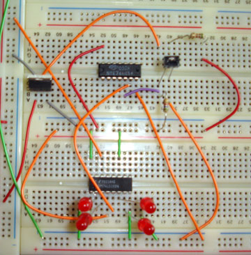
This is what I have working so far. There's a 5 volt regulator, a binary counter, a reflective sensor, and a Schmitt trigger.
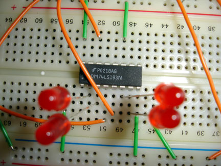
This is a closer view of the binary counter I'm using. It has 4 outputs that are connected to LEDs for testing purposes right now, but eventually will be hooked up to a 4-to-16 decoder. The clock input on it now is connected to the output of the Schmitt trigger.
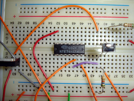
This is the Schmitt trigger. The input is taken from the collector of the optical reflective sensor I'm using. It's inverting the input and triggering the binary counter.
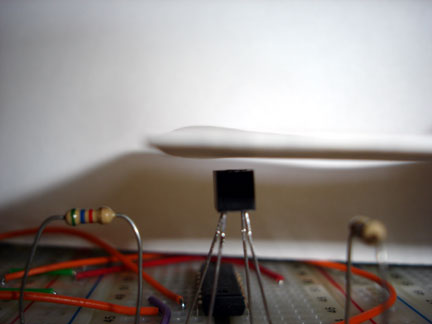
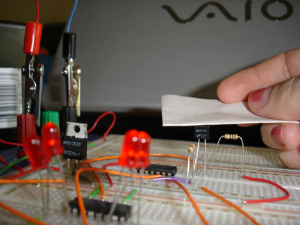
This sensor is what has worried me the most. I'd never used an optical reflective sensor before, but the datasheets made it sound like the part I needed for the project. I bought 4 with the hopes that they'd pull through, and so far they have lived up to their expectations. This picture was taken at the point where the sensor had JUST sensed an object in front of it, at possible 1/8 or 1/4 of an inch away. This is pretty useful, considering the only reflective distance mentioned on the datasheets was .05".
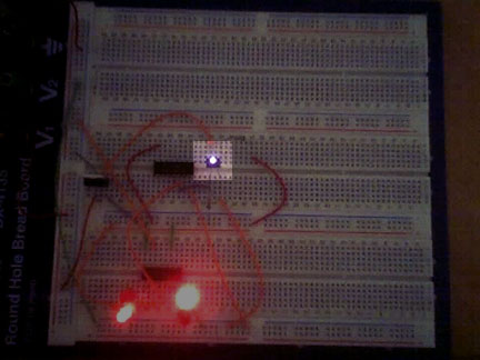
Here you can see the infrared emitting diode working on the reflective sensor. You can also see a couple of the red LEDs lit up.
And here is just a sideways look at the whole layout so far.
To see the set-up working, here's a short video.